Here's a bit of code for reading and displaying all 6 sensors:
//////////////////////////////////////////////////////////
// Simply reads the Razor 6DOF accelerometer/gyro and   //
// prints raw ADC values                                //
//////////////////////////////////////////////////////////

void setup(){
  analogReference(EXTERNAL);  // sets reference voltage to VREF
  Serial.begin(115200);
  delay(200);
}

void loop()
  {
  //Output the raw values
  Serial.print("Gyro x: ");
  Serial.print(analogRead(1));
  Serial.print(" | Gyro y: ");
  Serial.print(analogRead(0));
  Serial.print(" | Gyro z: ");
  Serial.print(analogRead(2));

  Serial.print("       Accel x: ");
  Serial.print(analogRead(5));
  Serial.print(" | Accel y: ");
  Serial.print(analogRead(4));
  Serial.print(" | Accel z: ");
  Serial.println(analogRead(3));

  delay(100);// slow down the serial output - Easier to read
}
If you use this code, just make sure to update the analogRead statements with your correct pins. With my board flat and close to level, I get the following 7 consecutive data readings:
Gyro x: 379 | Gyro y: 380 | Gyro z: 377       Accel x: 504 | Accel y: 508 | Accel z: 617
Gyro x: 379 | Gyro y: 380 | Gyro z: 377       Accel x: 504 | Accel y: 508 | Accel z: 618
Gyro x: 378 | Gyro y: 380 | Gyro z: 378       Accel x: 504 | Accel y: 509 | Accel z: 619
Gyro x: 379 | Gyro y: 381 | Gyro z: 377       Accel x: 505 | Accel y: 509 | Accel z: 618
Gyro x: 379 | Gyro y: 380 | Gyro z: 377       Accel x: 504 | Accel y: 508 | Accel z: 618
Gyro x: 379 | Gyro y: 381 | Gyro z: 377       Accel x: 504 | Accel y: 508 | Accel z: 618
Gyro x: 379 | Gyro y: 380 | Gyro z: 377       Accel x: 504 | Accel y: 509 | Accel z: 618
The numbers will fluctuate a little bit as you can see from my data. It's normal, caused by noise.
Next, turning those raw ADC values into useable numbers! The sensors each output a voltage somewhere between 0 and 3.3V. For the gyros, which measures rate (in deg/sec), they have a sensitivity of 3.33mV/deg/sec according to the spec sheet. The accelerometers, which measure gravitational acceleration (in g's), have a sensitivity of about 330mV/g. The ADC gives a value proportional to the voltage it receives, 0 to 1023 quids (10-bit resolution). Since the 6DOF board uses 3.3V, I hooked the Arduino's VREF pin to the 3.3V, which scales the ADC to the same 3.3V (as opposed to 5V). So the ADC will give me, for example, 1023 if it reads 3.3V. Or, about 512 quids for 1.65V (1023/1.65=512), etc. It's linear, so the math is easy.
Here's the basic equations for doing the conversions:
Gyro:Gyro_Rate = (Gyro_ADC_Value - Zero_Voltage_Value) * (3.3V/1023) / Gyro_Sensitivity
The zero_voltage_value is simply the initial ADC value of the sensor when it's not moving. You can read and store this value during setup. In the case of the gyro, when it's not moving, the rate should be zero, so we must zero out the gyro in the equation.
Even though the math is easy, there is nothing better than a worked-out example! In this example, I've read an ADC value 411 from the x-axis gyro during a rotation. My zero_voltage_value is 379 from my data above.
GyroRateX = (411-379) * (3.3/1023) / 0.00333  ----> (0.00333 is 3.33mV)
GyroRateX =  32 * 0.0032258 / 0.00333
GyroRateX = 30.999 deg/s
From this, I can see I'm rotating at a rate of about 31 degrees/second. Now how do use this to keep track of my overall angle of rotation? Easy! This can be done by taking regular readings and integrating them over a specified period of time.
Lets say I take readings every 20ms, or 0.020 seconds. My GyroRateX value gives me degrees/second. If I multiply that by 0.02sec, I'll get the total angle the sensor is rotated during that short period of time. This of course assumes the rate was constant over that time. I can keep track of my overall rotation angle by adding up these small rotations. Example: GyroAngleX += GyroRateX * 0.02
If you've not seen it, the "+=" symbology just says to add the calculated value on the right to GyroAngleX.
Accelerometer
I'm going to show two different ways of calculating angle of rotation from the accelerometer data. Although the common way of doing it is using force vectors, I wont show that here.
First method: The first part of the calculation is exactly the same as for the gyro. I need to zero the ADC readings, convert any remaining ADC values into quids, then convert that into voltage. The voltage can then be divided by the accelerometer sensitivity, like we did with the gyro.Accel_X = (Accel_ADC_Value - Zero_Voltage_Value) * (3.3V/1023) / Accel_Sensitivity
It should be noted that the zero_voltage_value in this case is with respect to the x-axis accelerometer. Now for a worked example:Accel_X = (558 - 504) * (3.3/1023) / 0.33 ----> (0.33 is 330mV)
Accel_X = 54 * 0.0032258 / 0.33
Accel_X = 0.528 G's
Now to convert this value into an angle, we can take the Arcsin of the value. The result will be in radians. Since 1 radian = 180/PI or 57.2957795 degrees, we can just multiply the result accordingly to get degrees.Accel_Angle_X = asin(Accel_X) * 57.2957795
Accel_Angle_X = asin(0.528) * 57.2957795
Accel_Angle_X = 0.556 * 57.2957795
Accel_Angle_X = 31.87 degrees
I had found this calculation through my research. It took me a minute to think about how on earth you could go from a G-force directly to a precise angle. But it's really pretty simple...
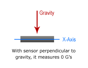
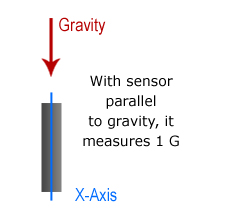
Firstly, this only works for the X and Y axis's. Basically, the accelerometers measure the force caused by gravity along the axis of the sensor. When the X and Y accel's are parallel with the Earth's surface, the force of gravity on the sensors is zero. When either sensor is perpendicular to the Earth's surface, it then measures 1-G. While at any other angle, the measured force will be between 0 and 1. Hence, as long as we're only measuring gravity (tilt angles), this equation works well.
Second method: This next method of calculation is what I've decided to use. It uses the Arduino's Map() function. I came upon this method here: bilder.org/?s=adxl335. It's simple, straight forward, and works really well. You'll want to read that page for a full explanation, which I'll only skim here.
Basically, for each axis, the map() function will take two different ranges and "re-map" a value from one range to the other. The two ranges are the min/max ADC values for each axis, and the other range is -90 to 90 degrees, which we want to map to. This is done for all 3 accelerometer axis's. The results are fed through a couple atan2 functions, which give us a final X and Y angle.
Here is the actual source code I use for this://The minimum and maximum values that came from
//the accelerometer...
//You very well may need to change these
int minValx = 403;
int maxValx = 610;
int minValy = 400;
int maxValy = 614;
int minValz = 413;
int maxValz = 619;
  //convert read values to degrees -90 to 90 - Needed for atan2
  int xAng = map(AN[3], minValx, maxValx, -90, 90);
  int yAng = map(AN[4], minValy, maxValy, -90, 90);
  int zAng = map(AN[5], minValz, maxValz, -90, 90);

  //Caculate 360deg values like so: atan2(-yAng, -zAng)
  //atan2 outputs the value of -π to π (radians)
  //We are then converting the radians to degrees
  AccAngleX = Rad2Deg * (atan2(-xAng, -zAng) + PI);
  AccAngleY = Rad2Deg * (atan2(-yAng, -zAng) + PI);
In the final AccAngle statements, the original code had -xAng and -yAng the other way around. It was causing my axis's to be reversed, so I swapped them, seems to have fixed it. I believe this is due to the physical orientaion that the sensor chips are mounted to each other.
Min/Max Values...
The above code showed the minimum and maximum values I obtained from my sensors. I created an easy Sketch for obtaining these. Run this following sketch and view the results in the Serial Monitor. For each axis, rotate it through its furthest extents (+-90deg). The numbers will update everytime a new min or max is read. Make sure not to exert any acceleration on the axis you're measuring though. You may need to support your board on a table as you're rotating it. The code:
// These hold accelerometer maximum/minimum values
int aX_max=0, aX_min=0, aY_max=0, aY_min=0, aZ_max=0, aZ_min=0;

// Raw data variables
int aX, aY, aZ;


void setup()
{
  analogReference(EXTERNAL);  // sets reference voltage to use voltage applied to VREF pin
  Serial.begin(115200);

  delay(100);  // give some time for warm-up

  // Read and set starting values
  aX = analogRead(5);	// <- make sure to set your pins here
  aY = analogRead(4);
  aZ = analogRead(3);

  aX_max = aX;
  aX_min = aX;
  aY_max = aY;
  aY_min = aY;
  aZ_max = aZ;
  aZ_min = aZ;

}

void loop()
{

  aX = analogRead(5);
  aY = analogRead(4);
  aZ = analogRead(3);


aX_max = max(aX_max, aX);
aX_min = min(aX_min, aX);
aY_max = max(aY_max, aY);
aY_min = min(aY_min, aY);
aZ_max = max(aZ_max, aZ);
aZ_min = min(aZ_min, aZ);

  Serial.print("Accelerometer... axis(min,max):    X(");
  Serial.print(aX_min);
  Serial.print(",");
  Serial.print(aX_max);
  Serial.print(")  Y(");
  Serial.print(aY_min);
  Serial.print(",");
  Serial.print(aY_max);
  Serial.print(")  Z(");
  Serial.print(aZ_min);
  Serial.print(",");
  Serial.print(aZ_max);


    Serial.println(" ");
delay(100);
}
Sensor Fusion
The next step is to take the calculated angles from both the gyros and accelerometers and combine them in a way that I can get a stable, accurate result. The gyro angles are very good and stable for the short term, but they can quickly drift and become inaccurate. The accels give me good angles over a longer period of time, but in the short run, they can be noisy. So I'll need to use the gyros as the base of my result, and correct towards the angles produced by the accelerometers over time. For this, I'm using a complementary filter of sorts, as described in this document, filter.pdf. The general equation is:
angle = (0.98)*(angle + gyro * dt) + (0.02)*(x_acc);
I've had excellent results with this, with no noticeable lag time using readings at 10ms intervals.
Here is the complete code for reading values from the 6DOF board and converting the ADC values to useable angles. The print output is formatted to be used with my attitude display software. Note: This code, and my software, do NOT provide full 360 degrees of freedom (other than Z-axis). This code gives me exactly what I need, and only what I need, which is +-90 degrees of both pitch and yaw. Remember, this entire project is purpose-built for fixed-wing UAV purposes, only. You can of course modify the code for full 360-degree resolution, but I can not assist with that.
#define Gyro_Sens 0.00333 // Gyro sensitivity = 3.33mV/deg/s
#define VPQ 0.00322581 // Volts Per Quid --- value of 3.3V/1023
#define ADC_Avg_Num  100.// Number of averaging readings for calibration
#define Rad2Deg 57.2957795 // 1 radian = 57.2957795 degrees
#define Deg2Rad 0.0174532925 // 0.0174532925 rads = 1 deg

//The minimum and maximum values that came from
//the accelerometer...
//You very well may need to change these
int minValx = 403;
int maxValx = 610;

int minValy = 401;
int maxValy = 614;

int minValz = 413;
int maxValz = 619;

//Calibration variables
float Gx_Cal, Gy_Cal, Gz_Cal;

float GyroRateX=0, GyroRateY=0, GyroAngleZ=0, GyroAngleZ_dt=0;
float AccAngleX=0, AccAngleY=0, AccAngleZ=0;

float Pitch, Yaw, Roll;

int AN[6];  // Hold analogRead data

unsigned long pre_time, print_clock=0;
float dtime;


void setup()
{
  analogReference(EXTERNAL);  // sets reference voltage to use voltage applied to VREF pin
  Serial.begin(115200);
  delay(300);  // Give things time to "warm-up"

  Calibrate(); // Calibrate sensors
  pre_time = millis(); //store current time to be used as "previous" time
}


void loop()
{

  if(millis()-pre_time>=20) // Read ADC and does Calculations every 20ms
  {
    dtime=millis()-pre_time;  //current time - previous time
    pre_time = millis(); //store current time to be used as "previous" time
    dtime=dtime/1000.;

    Read_ADC();
    Calculate();
  }


  if(millis()-print_clock>=50)  //print every 50ms
  {
  Serial.print(Pitch);
  Serial.print(",");
  Serial.print(Roll);
  Serial.print(",");
  Serial.println(Yaw);

  print_clock=millis();  // store current time

  } //end if


}


///////////////////////////////////////////////////////////////////////
////////////////////////   Functions    ///////////////////////////////
///////////////////////////////////////////////////////////////////////


void Read_ADC(void)
{

  AN[0] = analogRead(1); // Gyro_X
  AN[1] = analogRead(0); // Gyro_Y
  AN[2] = analogRead(2); // Gyro_Z
  AN[3] = analogRead(5); // Acc_X
  AN[4] = analogRead(4); // Acc_Y
  AN[5] = analogRead(3); // Acc_Z
}


void Calculate(void)
{

// Gyro portion
//----------------------------------------------------------------
  GyroRateX = -1.0*dtime * (((AN[0]*3.3)/1023.-Gx_Cal)/Gyro_Sens);
  GyroRateY = dtime * (((AN[1]*3.3)/1023.-Gy_Cal)/Gyro_Sens);

  GyroAngleZ_dt = dtime * (((AN[2]*3.3)/1023.-Gz_Cal)/Gyro_Sens);
  GyroAngleZ += -1.0 * GyroAngleZ_dt * (1/(cos(Deg2Rad*Roll))); // convert Roll angle to Rads, find sin to use as scaler for Yaw

  if(GyroAngleZ<0) GyroAngleZ+=360;    // Keep within range of 0-360 deg
  if(GyroAngleZ>=360) GyroAngleZ-=360;
//----------------------------------------------------------------

  //convert read values to degrees -90 to 90 - Needed for atan2
  int xAng = map(AN[3], minValx, maxValx, -90, 90);
  int yAng = map(AN[4], minValy, maxValy, -90, 90);
  int zAng = map(AN[5], minValz, maxValz, -90, 90);

  //Caculate 360deg values like so: atan2(-yAng, -zAng)
  //atan2 outputs the value of -π to π (radians)
  //We are then converting the radians to degrees
  AccAngleX = Rad2Deg * (atan2(-xAng, -zAng) + PI);
  AccAngleY = Rad2Deg * (atan2(-yAng, -zAng) + PI);

  // Keep angles between +-180deg
  if(AccAngleX>180) AccAngleX=AccAngleX-360;

  if(AccAngleY<=180) AccAngleY=-1.0*AccAngleY;
  if(AccAngleY>180) AccAngleY=360-AccAngleY;

  // Final values...
  Roll = (0.98)*(Roll + GyroRateX) + (0.02)*(AccAngleX);
  Pitch = (0.98)*(Pitch + GyroRateY) + (0.02)*(AccAngleY);
  Yaw = GyroAngleZ;
}


// Reads and averages ADC values for calibration
float Avg_ADC(int ADC_In)
{
  long ADC_Temp=0;
  for(int i=0; i<ADC_Avg_Num; i++)
  {
    ADC_Temp = ADC_Temp+analogRead(ADC_In);
    delay(10); // Delay 10ms due to gyro bandwidth limit of 140Hz (~7.1ms)
  }
  return VPQ*(ADC_Temp/ADC_Avg_Num); //Average ADC, convert to volts
}

void Calibrate(void)
{
  Gx_Cal = Avg_ADC(1); // Gyro_x on pin 1
  Gy_Cal = Avg_ADC(0); // Gyro_y on pin 0
  Gz_Cal = Avg_ADC(2); // Gyro_z on pin 2
}

////////////////////////
//////// END CODE //////
////////////////////////
You can see a video of this code in action on the next page, Attitude Indicator In C#.
One piece of the code which I did not talk about is the section calculating the value for GyroAngleZ, as this is an active work-in-progress. Picture the 6DOF board installed on an aircraft. With both the aircraft and the 6DOF board flat and level, the Z-axis gyro accurately describes the yaw of the aircraft. However, if the aircraft was in a turn, only a fraction of the turn would be read by the Z-gyro. So I needed a way to account for the change in roll angle with respect to the Z-gyro. I assume aircraft pitch is constant. The code above shows the mathematical formula I came up with, although it may need some more work.
Still left to do... Next to do is implement code for fusing the Z-gyr


RECENT COMMENT